IEC TS 61400-13 pdf download
IEC TS 61400-13 pdf download.Wind turbine generator systems
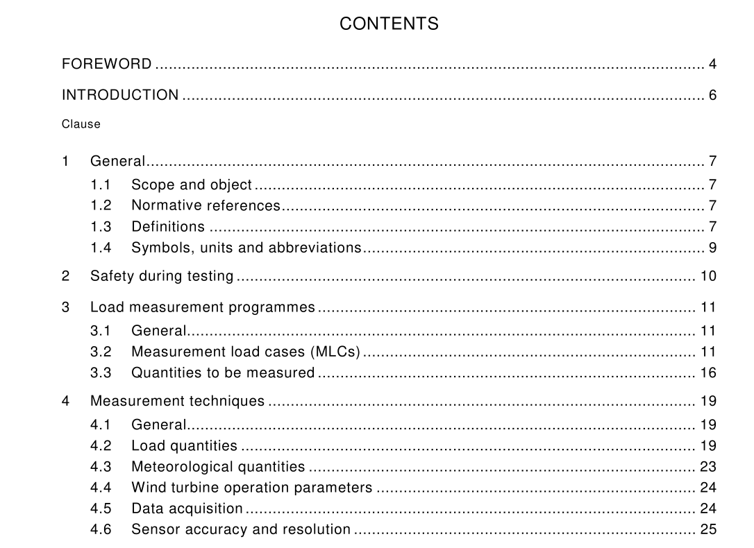
1 General
1 .1 Scope and object
This part of IEC 61 400 deals with mechanical load measurements on wind turbines. It mainly focuses on large (>40 m 2 ) electricity generating horizontal axis wind turbines. However, the methods described might be applicable to other wind turbines as well (for example, mechanical water pumpers, vertical axis turbines). The object of this specification is to describe the methodology and corresponding techniques for the experimental determination of the mechanical loading on wind turbines. This technical specification is intended to act as a guide for carrying out measurements used for verification of codes and/or for direct determination of the structural loading. This specification is not only intended as one coherent measurement specification but can also be used for more limited measurement campaigns.
1 .2 Normative references
The following normative documents contain provisions which, through reference in this text, constitute provisions of this part of IEC 61 400. For dated references, subsequent amendments to, or revisions of, any of these publications do not apply. However, parties to agreements based on this part of IEC 61 400 are encouraged to investigate the possibility of applying the most recent editions of the normative documents indicated below. For undated references, the latest edition of the normative document referred to applies. Members of IEC and ISO maintain registers of currently valid International Standards. IEC 60050(41 5):1 999 , International Electrotechnical Vocabulary (IEV) – Part 41 5: Wind turbine generator systems IEC 61 400-1 :1 999, Wind turbine generator systems – Part 1 : Safety requirements IEC 61 400-1 2:1 998, Wind turbine generator systems – Part 1 2: Wind turbine power performance testing ISO 1 995, Guide to the expression of uncertainty in measurement
1 .3 Definitions
For the purpose of this technical specification, the definitions related to wind turbine systems or wind energy in general of IEC 60050(41 5) and the following definitions apply. 1 .3.1 blade rotating aerodynamically active part of the rotor 1 .3.2 blade root that part of the rotor blade that is connected to the hub of the rotor 1 .3.3 calibration load forces and moments applied during calibration 1 .3.4 capture matrix organization of the measured time series according to mean wind speeds and turbulence intensities 1 .3.5 chord length of a reference straight line (the chord line) that joins, by certain defined conventions, the leading and trailing edges of a blade airfoil cross-section 1 .3.6 chord line reference straight line that joins, by certain defined conventions, the leading and trailing edges of a blade airfoil cross-section 1 .3.7 design loads loads that the turbine is designed to withstand. They are obtained by applying the appropriate partial load factors to the characteristic values 1 .3.8 flap direction which is perpendicular to the swept surface of the undeformed rotor blade axis 1 .3.9 hub fixture for attaching the blades or blade assembly to the rotor shaft 1 .3.1 0 lead-lag direction which is parallel to the plane of the swept surface and perpendicular to the longitudinal axis of the undeformed rotor blade 1 .3.1 1 nacelle housing which contains the drive train and other equipment on the top of a HAWT tower 1 .3.1 2 natural frequency (eigenfrequency) frequency at which a structure will choose to vibrate when perturbed and allowed to vibrate freely 1 .3.1 3 outboard towards the blade tip 1 .3.1 4 partial safety factors factors that are applied to loads and material strengths to account for uncertainties in the representative (characteristic) values 1 .3.1 5 radial position distance from the rotor centre in a plane perpendicular to the rotor axis1 .3.1 6 rotor centre point on the main shaft in the plane perpendicular to the main shaft that contains the blade co-ordinate origin of the reference blade 1 .3.1 7 rotor plane plane perpendicular to the main shaft and which includes the rotor centre 1 .3.1 8 spanwise direction parallel to the longitudinal axis of a rotor blade 1 .3.1 9 steady-state operation state of operation of the turbine during which it remains in a steady state such as during power production, power production + fault condition and when parked or idling and for which the external conditions also remain essentially steady or characterized by stationary random processes for the duration of the measurement 1 .3.20 transient event event during which the state of operation of the wind turbine changes, such as during shut-down 1 .3.21 test load forces and moments applied during a test 1 .3.22 turbulence intensity turbulence intensity is the ratio of the standard deviation of the wind speed in a given time interval to the mean wind speed in the same time interval 1 .3.23 yaw position angle between the vertical projection of the centre line of the main shaft on the tower base and the X-axis of the tower co-ordinate system (which is to be defined as appropriate according to the site and the shape of the tower cross-section). The yaw position is positive rotating counter-clockwise (top view)
