ISO IEC 18004 pdf download
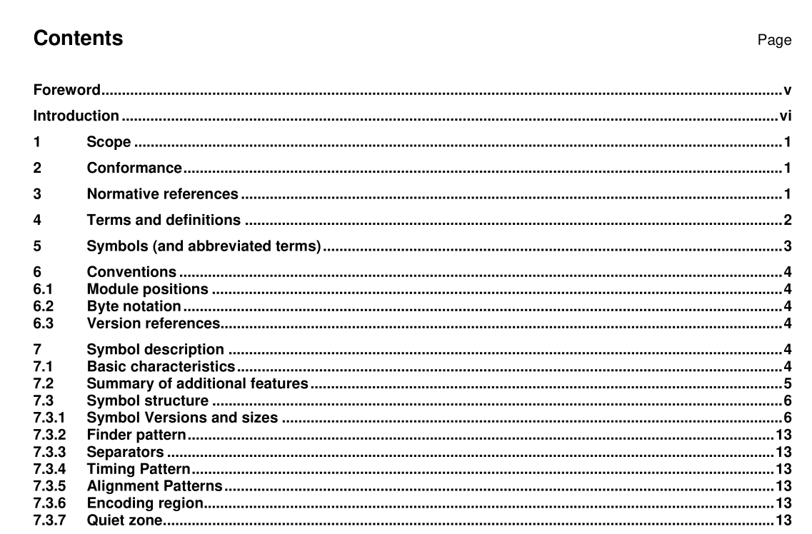
ISO IEC 18004 pdf download.Information technology — Automatic identification and data capture techniques — Bar code symbology — QR Code
4 Terms and definitions
For the purposes of this International Standard, the terms and definitions given in EN 1 556 and the following apply. 4.1 Alignment Pattern fixed reference pattern in defined positions in a matrix symbology, which enables the decode software to re- synchronise the coordinate mapping of the image modules in the event of moderate amounts of distortion of the image 4.2 Character Count Indicator bit sequence which defines the data string length in a mode 4.3 ECI designator six-digit number identifying a specific ECI assignment 4.4 encoding region region of the symbol not occupied by function patterns and available for encodation of data and error correction codewords 4.5 Extended Channel Interpretation (ECI) protocol used in some symbologies that allows the output data stream to have interpretations different from that of the default character set 4.6 Extension Pattern in Model 1 symbols, a function pattern which does not encode data 4.7 Format Information function pattern containing information on the error correction level applied to the symbol and on the masking pattern used, essential to enable the remainder of the encoding region to be decoded 4.8 function pattern overhead component of the symbol required for location of the symbol or identification of its characteristics to assist in decoding 4.9 Mask Pattern Reference three-bit identifier of the masking patterns applied to the symbol 4.10 masking process of XORing the bit pattern in the encoding region with a masking pattern to provide a symbol with more evenly balanced numbers of dark and light modules and reduced occurrence of patterns which would interfere with fast processing of the image 4.11 mode method of representing a defined character set as a bit string 4.12 Mode Indicator four-bit identifier indicating in which mode the next data sequence is encoded 4.13 Padding Bit 0 bit, not representing data, used to fill empty positions of the final codeword after the Terminator in a data bit string 4.14 Position Detection Pattern one of three identical components of the Finder Pattern 4.15 Remainder Bit 0 bit, not representing data, used to fill empty positions of the symbol encoding region after the final symbol character, where the encoding region does not divide exactly into eight-bit symbol characters 4.16 Remainder Codeword Pad Codeword used to fill empty codeword positions to complete the symbol if the total number of data and error correction codewords does not exactly fill its nominal capacity NOTE The Remainder codewords come after the error correction codewords. 4.17 segment sequence of data encoded according to the rules of one ECI or encodation mode 4.18 Separator function pattern of all light modules, one module wide, separating the Position Detection Patterns from the rest of the symbol 4.19 Terminator bit pattern 0000 used to end the bit string representing data 4.20 Timing Pattern alternating sequence of dark and light modules enabling module coordinates in the symbol to be determined 4.21 Version size of the symbol represented in terms of its position in the sequence of permissible sizes from 21 ? 21 modules (Version 1 ) to 1 77 ? 1 77 (Version 40) modules NOTE May also indicate the error correction level applied to the symbol. 4.22 Version Information in Model 2 symbols, a function pattern containing information on the symbol version together with error correction bits for this data
6 Conventions
6.1 Module positions For ease of reference, module positions are defined by their row and column coordinates in the symbol, in the form (i, j) where i designates the row (counting from the top downwards) and j the column (counting from left to right) in which the module is located, with counting commencing at 0. Module (0, 0) is therefore located at the upper left corner of the symbol. 6.2 Byte notation Byte contents are shown as hexadecimal values. 6.3 Version references Symbol versions are referred to in the form Version V-E where V identifies the version number (1 – 40) and E indicates the error correction level (L, M, Q, H).
