IEC 61986 pdf download
IEC 61986 pdf download.Rotating electrical machines – Equivalent loading and super-position techniques – Indirect testing to determine temperature rise
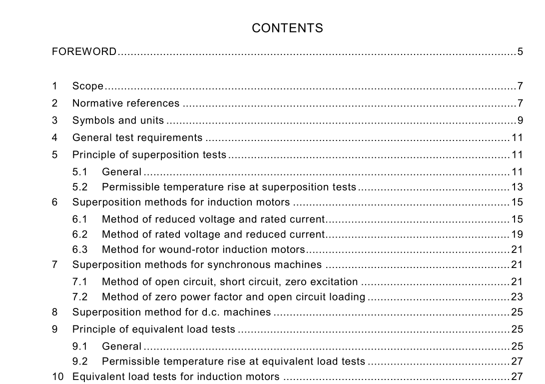
4 General test requirements
Measurement of the electrical parameters shall be made as follows. a) The class of accuracy of measuring instruments shall be not greater than 0,2, with the exception of wattmeters with cos ϕ lower than 0,5 and frequency meters, which may have accuracy class 0,5. b) The measuring range of the instruments shall be chosen with a view to the measured values being higher than 30 % of the full-scale range. These requirements need not be complied with in the case of the three-phase power measurement by means of two wattmeters, but the currents and voltages in the measured circuits shall be at least 20 % of the rated currents and voltages of the wattmeters being used. The range of the other measuring instruments shall be chosen in such a way that the measuring errors are not increased. c) The waveform and dissymmetry of the supply voltage at the machine terminals shall be in accordance with the requirements of 6.1 to 6.5 of IEC 60034-1. d) Each line current shall be measured. If these are unequal, the arithmetic average value shall be used to determine the machine operating point. e) Power input to a three-phase machine may be measured by two single-phase wattmeters connected as in the two-wattmeter method, or one polyphase wattmeter, or three single- phase wattmeters. The total power read on a wattmeter shall be reduced by the amount of the I 2 R loss in the voltage circuits or in the current circuits of the instruments according to their connection whenever this loss is a measurable portion of the total power. There is no need to reduce the total power read on a wattmeter by the amount of the I 2 R losses for digital measuring instruments. All the electrical quantities to be measured are root-mean-square values unless otherwise indicated.
5 Principle of superposition tests
5.1 General Superposition tests may be applied to any d.c. or a.c. machine. The method comprises a series of tests at operating conditions other than rated load, for example, reduced load, no load, short circuit, reduced voltage, leading (underexcited) or lagging (overexcited) reactive load. The method allows the full-load temperature rise of various component parts of the machine to be deduced. For each component, the loss shall be known at each particular test condition and at full load. The tests should be undertaken with cooling conditions the same as when operating at rated load. Hence, a locked rotor test will not be suitable as the air-flow distribution and magnitudes will be incorrect.The method is based on the principle that the coefficients K do not change from test to test, i.e. that the cooling conditions are invariable between tests, which requires the speed to be the same in each test. The method is also based on the principle of the linear thermal conditions so that temperature rises in one case can be added to those for another case. It requires the losses in the relevant component parts to be known sufficiently accurately for each case, either by calculation or measurement. When the tests have been completed and the equations compiled, then by simple arithmetic the coefficients K can be derived. These are then used in a final equation with the losses for the rated load condition in order to calculate the temperature rise of component 1. By similar means, the temperature rises at rated load of components 2 and 3 can be derived. If any component loss is temperature dependent (for example, stator copper loss), then the calculation procedure has to be repeated using values for the loss corrected for the estimated temperature rise. It is probably necessary to do this iteration once only. The method may be used to determine the temperature rise of any component at any load if the losses at that load are known. The heat transfer coefficients (K 12 , etc.) may be useful in other thermal modelling studies, for example, in analysing the response to supply unbalance, voltage reduction, etc.
