IEC 61922 pdf download
IEC 61922 pdf download.High-frequency induction heating installations – Test methods for the determination of power output of the generator
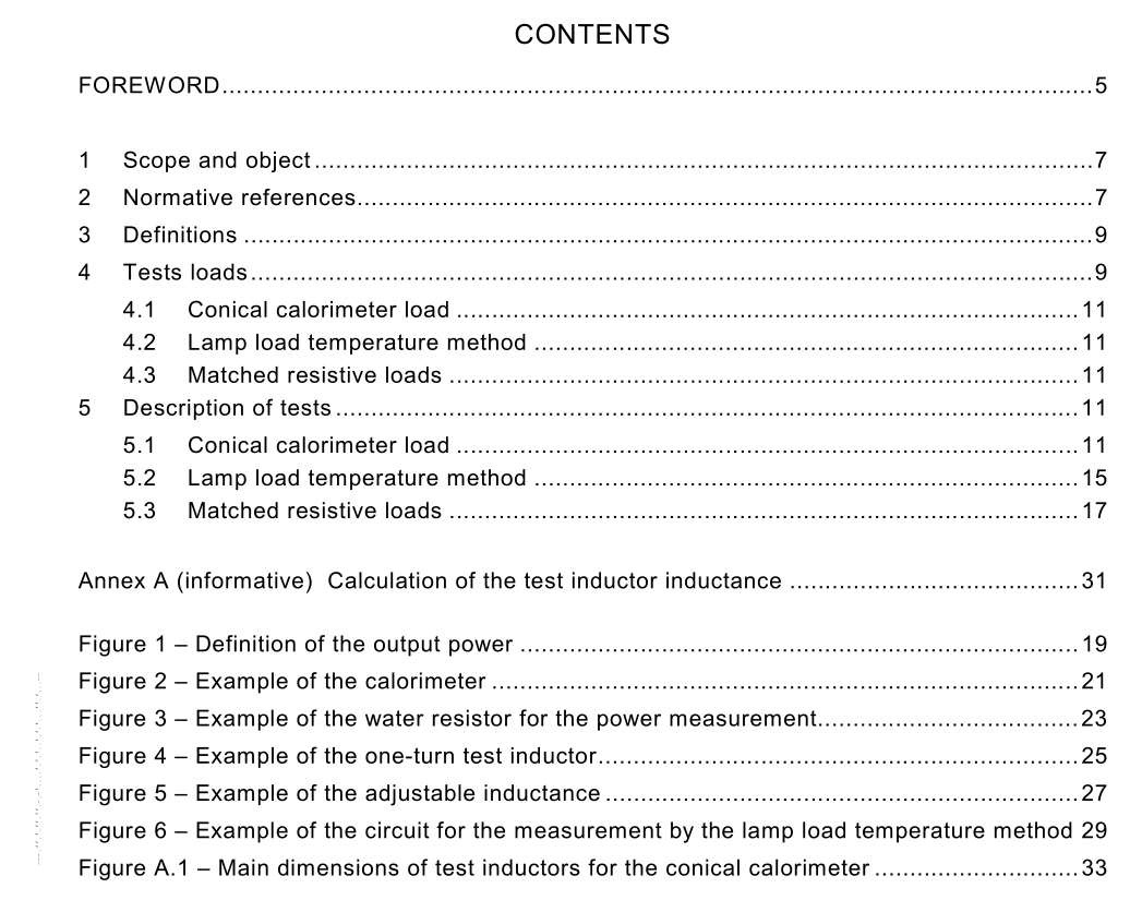
1 Scope and object
This International Standard is applicable to industrial radio- or high-frequency induction heating installations used for the purpose of thermal applications (e.g. for surface hardening, welding, soldering, melting, forging, zone refining of semiconductors, etc.). This standard relates to high-frequency induction heating installations in the frequency range up to 300 MHz for power levels of 500 W and above, comprising high-frequency generators and inductors together with necessary mechanical devices for charge handling (e.g. hardening machines). The main purpose of this standard is to provide the test methods for the determination of output power of industrial high-frequency induction heating power sources. Loads as described in this standard may be used in compliance assessment of electromagnetic compatibility according to CISPR 11. This standard relates to generator capacity of operation under continuous rated conditions as specified by the manufacturer. The methods of measurement of power output of generators operating in pulse mode with short duty cycles (e.g. the adiabatic calorimeter) are under consideration. Electronic systems of power measurement are commercially available, but care must be taken in their application because accuracy can not be guaranteed, particularly at higher frequencies. These instruments require high current transformers and voltage transformers for the output power measurements and they also are subject to errors at higher frequencies. These methods require expert knowledge for successful application and therefore are not detailed in this standard.
3 Definitions
For the purposes of this International Standard, the definitions given in IEC 60050-841, IEC 60519-1 and IEC 60519-3 as well as the following, apply. 3.1 high-frequency output power power measured at the power output terminals of the generator, feeding to the test load as defined in this standard NOTE This definition is explained in figure 1. The left side of the drawing contains the generator and is limited by its two output terminals. The load is connected to these terminals. All power that appears outside of the generator case is defined as the output power of the generator. It comprises the power dissipated in the inductor, power leads, calorimeter, etc. 3.2 calorimeter device for the measurement of high-frequency power, which consists of a part cooled by water, under controlled flow and measured temperature difference between water inlet and outlet temperatures NOTE This part is made of steel or other conductive material into which high-frequency currents are induced. 3.3 surface power density quotient of the power and the active surface of the calorimeter 3.4 loop inductor inductor in the shape of a loop brought close to the load without forming a full circle around it 3.5 test load equipment consisting of the connection leads, the inductor and the calorimeter. If a resistor without reactive elements is used as a load, an auxiliary resonant circuit is used for the elimination of the harmonic power. If this auxiliary circuit is not part of the generator, the losses in this circuit are measured with the losses in the other parts of the test load
5 Description of tests
Electromagnetic fields in places occupied by attending personnel shall conform with national and/or international safety regulations. High-frequency fields should not affect measuring devices. In particular, mercury thermometers should not be placed in magnetic fields of great strength. For all listed calorimetric measurement methods, care shall be taken that the outlet temperature will be measured as close as possible to the load. Besides the listed calorimetric methods direct electric measurement methods can also be used. In this case, the current and voltage transformers as well as the measurement instrument itself must be suitable for the power factor, the working frequency and its harmonics. The sum of all errors shall not exceed 5 %. NOTE In special cases when it is necessary to measure powers in the range from 100 W to 500 W, the errors greater than 5 % should be accepted. 5.1 Conical calorimeter load A typical example is shown in figure 2. External walls of the calorimeter are made of carbon steel. The use of high alloy steel is not recommended, because of lower magnetic permeability than most loads used in practical applications. The thickness of walls shall provide adequate mechanical strength (also in the case of overheating). The inner cone can also be made of steel. The cross section of those parts, where water flows, should be, if possible uniform and such as to provide suitable water velocity for best heat exchange.
