IEC 61834-1 pdf download
IEC 61834-1 pdf download.Helical-scan digital video cassette recording system using 6,35 mm magnetic tape for consumer use (525-60, 625-50, 1125-60 and 1250-50 systems)
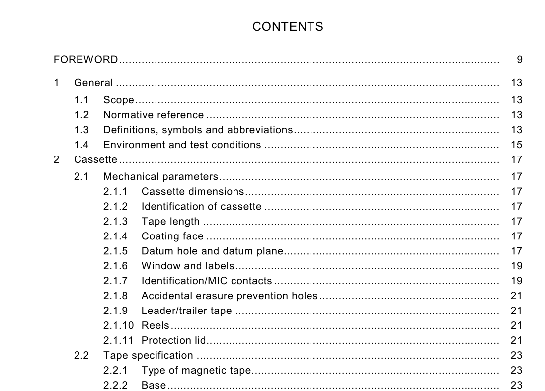
1 General
1.1 Scope This part of IEC 61 834 specifies the content, format and recording method of the data blocks forming the helical records on the tape. It describes the common specifications for cassettes, modulation method, magnetization and basic system data, for helical-scan digital video cassette recording system using 6,35 mm (1 /4 inch) magnetic tape. The object of this standard is to define the electrical and mechanical characteristics of equipment which will provide for the interchangeability of recorded cassettes. 1.2 Normative reference The following normative document contains provisions which, through reference in this text, constitute provisions of this International Standard. At the time of publication, the edition indicated was valid. All normative documents are subject to revision, and parties to agreements based on this International standard are encouraged to investigate the possibility of applying the most recent edition of the normative document listed below. Members of IEC and ISO maintain registers of currently valid International Standards. IEC 61 834-2:1 998, Recording – Helical-scan digital video cassette recording system using 6,35 mm magnetic tape for consumer use (525-60, 625-50, 1 125-60 and 1 250-50 systems) – Part 2: SD format for 525-60 and 625-50 systems
2 Cassette
2.1 Mechanical parameters 2.1.1 Cassette dimensions The dimensions of the two types of cassettes shall be in accordance with figures 1 to 22 and symmetrical in form unless specified otherwise. The dimensions of the cassette shall correspond to the dimensions indicated for surfaces including the radii of the ridgelines outlining the cassette which shall be 0,3 mm or less, unless specified otherwise. General tolerances for dimensions shall be as specified in table 1 except for special specified tolerances. The dimensions marked with ! are nominal values. 2.1 .2 Identification of cassette The sizes of the two types of cassettes shall be identified as follows: Standard cassette (approximate size: 1 25,0 mm × 78,0 mm × 1 4,6 mm) Small cassette (approximate size: 66,0 mm × 48,0 mm × 1 2,2 mm).
2.1.6 Window and labels Window and label areas shall be as specified in figures 1 and 1 2. Windows and labels shall not extend beyond the height of the holding area 1 within the area 7 mm from both sides of the cassette where the height is measured from datum plane Z. Labels attached to the cassette shall not extend beyond the external dimensions as shown in figures 1 and 1 2 and shall not interfere with the identification contacts, the hub drive and the support mechanism. 2.1.7 Identification/MIC contacts Both cassettes with ID board and cassettes with memory (MIC) shall have four electrical contacts whose dimensions and locations shall be as specified in figures 1 1 and 22. Characteristics between these contacts and connectors shall be as described below on condition that the ID board or MIC is inside a cassette. The contact force of each connector shall be between 0,25 N to 0,4 N. The contact resistance value of each connector shall be less than 0,5 Ω. The contact impedance of each connector shall be less than 1 ,0 Ω. The contact resistance value is measured between each pair of connectors on condition that two corresponded contacts are short-circuited and the supplied d.c. current is between 50 µA and 300 mA. The contact impedance is measured between each pair of connectors on condition that two corresponded contacts are short-circuited and supplied a.c. peak current is 1 0 mA at 4 MHz. For cassette with ID board The contact number 1 shall indicate the tape thickness. The contact number 2 shall indicate the tape type. The contact number 3 shall indicate the tape grade. The contact number 4 shall be ground level. The resistance value between contact numbers 1 to 3 and the contact number 4 designates the cassette identifications as specified in table 2. For cassette with memory (MIC) The contact number 1 shall be VDD level. The contact number 2 shall be used for SDA. The contact number 3 shall be used for SCK. The contact number 4 shall be ground level.
