API Std 617 pdf download
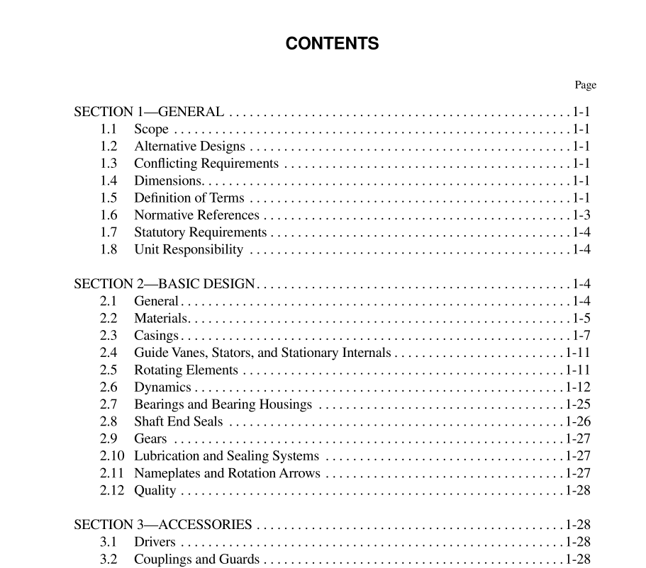
API Std 617 pdf download.Axial and Centrifugal Compressors and Expander-compressors for Petroleum, Chemical and Gas Industry Services
1.5 DEFINITION OF TERMS
Terms used in all chapters of this standard are defined in 1.5.1 through 1.5.54. Annexes 2C, 3C, and 4C on nomencla- ture are located in each subsequent chapter of this specification. 1.5.1 axially split: A joint that is parallel to the shaft centerline. 1.5.2 compressor or expander section: A series of compression or expansion stages between which there is no intercooling or reheating, or loss or gain in flow (i.e., no side streams, bypassing or injection), and whose rotational speeds are in fixed relationship (ratio) to each other. 1.5.3 compressor rated point: The intersection on the 100% speed curve corresponding to the highest capacity of any specified operating point. Note: This is generally a derived point rather than an actual operat- ing point (see Figure 2.1-1a for a graphical representation). 1.5.4 critical speed: A shaft rotational speed at which the rotor-bearing-support system is in a state of resonance. 1.5.5 design: A term that may be used by the equipment manufacturer to describe various parameters such as design power, design pressure, design temperature, or design speed. Note: This terminology should be used only by the equipment designer and manufacturer and not in the purchaser’s specifications. 1.5.6 flammable fluid: The definition of a flammable fluid is covered in detail in NFPA 30. 1.5.7 gear service factor (sf): The factor that is applied to the tooth pitting index and the bending stress number, depending upon the characteristics of the driver and the driven equipment, to account for differences in potential overload, shock load, and/or continuous oscillatory torque characteristics. 1.5.8 gear wheel (bullgear): The lowest speed rotor in a gearbox. 1.5.9 gearing: The pinion(s) and gear wheel combina- tion(s). A gear mesh is a pinion and gear wheel that operates together. A gear wheel may mesh with more than one pinion, and therefore be part of more than one gear mesh. 1.5.12 hysteresis or internal friction dampening causes a phase difference between the stress and strain in any material under cyclical load. This phase difference produces the characteristic hysteric loop on a stress-strain diagram and thus, a destabilizing dampening force. 1.5.13 informative element: A reference which is pro- vided for information and is intended to assist in the under- standing or use of the standard. Compliance with an informative element is not mandated. Note: An annex may be informative or normative as indicated. 1.5.14 inlet volume flow: The flow rate expressed in volume flow units at the conditions of pressure, temperature, compressibility, and gas composition, including moisture, at the equipment inlet flange. 1.5.15 machine: The compressor or expander. 1.5.16 maximum allowable temperature: The maxi- mum continuous temperature for which the manufacturer has designed the equipment (or any part to which the term is referred). Note: The maximum allowable temperature is usually set by mate- rial considerations. This may be the material of the casing or a tem- perature limit imposed by a gasket or O-ring. The material strength i.e., yield point, or ultimate strength is temperature dependent. A component’s stress level can depend on operating pressure. Thus, the margin between the strength limit of the material and the operat- ing stresses depends on both the materials operating temperature and the components stress level. If the temperature is lowered, the mate- rials strength increases and the stress level of the component may increase. This is the reason for associating the maximum allowable temperature to the maximum specified operating pressure.
