API Spec 7F pdf download
API Spec 7F pdf download.Specification for Oil Field Chain and Sprockets
1 Scope
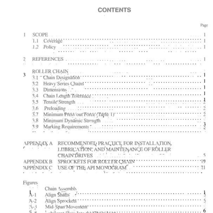
1.1 COVERAGE This specification covers the manufacture of the compo-. nents for, and the assembly and packaging of, single and multiple strand, number 40 through 240, standard and heavy series roller chains for. oil field application’s, including chain designation, chain length tolerance, tensile strength specif- cations, pin and bushing press-out specifications, and dynamic test requirements.” Eor informational purposes, appendices have . been included on recommendations for, installation, lubrication, and maintenance of oil tield chain drives and a basic descrip. tion of roller chain sproskets. 1.2 POLICY American Petroleum Institute (APD) specifigations are pub- lished as an aid to procurement of stahdardized equipment and materials. It must be noted that this specification goes beyond the requirements of other existing standards and sipec- ifications but does not preclude any party; from manufacturing chains that meet the requirementg of APf Spec 7E
3.5 TENSILE STRENGTH
3.5.1 Single Strand Chain Standard and heavy series ging le strand chain meeting the requirements of this specification will have a minimum ultj- mate tensile strength equa! t0 or greater than the yalues listed inTable 1. 3.5.2 Multiple Strand Chain For multiple strand chain, the minimum ultimate tensile strength equals hat of the single strand multiplied by the number of strands. 3.5.3 Minimum Ultimate Tensile Strength Minimum Ulimate Tensile Strength (MUTS), for chains covered by this specification, is defined in ASME B29.1. Chains eqvered by this specification shall have a MUTS equal to, oF greater thant, the yalues listed, in Table 1. MUTS is not a measure of the load at which a chain may be applied; it is indicative only of the tensile strengh quality of the chain. Any chain tests made to verify the MUTS set by this speci- ficaton are to be considered destructive. Consequently, all chain specimens subjected to such tests, failed or otherwise; are deemed unfit for application purposes. 3.6 PRELOADING Chains covered by this specification shall be preloaded during manufacture to a tensile load of at least 30% of the Minimum Ultimate Tensile Strength listed in Table 1. 3.7 MINIMUM PRESS-OUT FORCE (TABLE 1) These yalucs represent the minimum force, in pounds (or newtons), required to start movement of a single pin or bush- ing in a single link plate. The purpose of these values is 10 proyide for the testing of pin and bushing retention character- istics, This is jindicatiye of the aperture condition in the link plates and the interference fits of the pins and bushings in their respective link plates. 3.7.1 Pin and Pin-link Plates Chain link gassemblies that are assembled with riveted pin- heads shall have the rivet remeved, exercising eare not t0 remove the link plate metal below the surface of the link plate. One of the link plates shall be removed carefully to avoid destroying the jcint integrity between the plns and the link plates. The remaining plate shall be placed In a hydraulis cally or mechanically operated testing machine with the pin link level and supported to preyent movement when pressure is applied. A single axial load shall be slowly applied to the pin, pressing the pin Qut of the joint toward the inside of the plate. A force less than the specified press-out load, as appli- cable for the subject chain, shall constitute failure of the tesl, 3.7.2 Roller Link Plate Onc of the roller. link plates shall be removed psing the same method as described for the pin link. Remove the two rollers ficom the bushings and place the plate with the [Wo bushings in the testing machine with the plate supported po prevent movement when pressure is applied. A single axial load shall be slowly applied to the end of the bushing, press: ing the bushing out of the plate. 同load thal is less than the specified pressout load shall constitute failure of the test. 3.8 MINIMUM DYNAMIC STRENGTH Standaro and heavy, series single strand hain coniomng to this specfication shall be capable, of surviving a conformanice test at the minimum dynamic strength listed in Table 1 Con necting links, offset liniks, and muitiple strand chains are not subject to the conformange test. 3.8.1 Conformance,Test Initially, the manufasturer shall conduct a ponformange test at least one representative sample from each design family of oil field chain. A design family, being defityed as’ different Sstzecs of chain designed t the sam’e parameters, and manufac-. fured by the same processing operations.
