API Spec 16F pdf download
API Spec 16F pdf download.Specification for Marine Drilling Riser Equipment
1 Scope
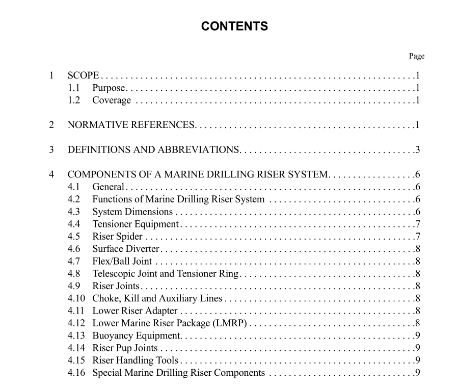
1.1 PURPOSE These specifications establish standards of performance and quality for the design, manufacture, and fabrication of marine drilling riser equipment used in conjunction with a subsea Blowout Preventer (BOP) Stack. 1.2 COVERAGE This specification provides the requirements for the following major subsystems in the marine drilling riser system: a. Riser tensioner equipment.* b. Flex/ball joints.* c. Choke, kill and auxiliary lines. d. Drape hoses and jumper lines for flex/ball joints. e. Telescopic joint (slip joint) and tensioner ring.* f. Riser joints.* g. Buoyancy equipment* (only syntactic foam modules eligible for API Monogram). h. Riser running equipment.* i. Special riser system components. j. Lower riser adapter.* Note: Only those subsystems above that are marked with an asterisk may be considered for API monogramming. Section 4 of the specification gives a general description of each of these components listed above. Section 5 provides general design requirements for riser components. Section 6 addresses materials, including the riser pipe. Paragraph 6.13 covers welding of couplings to riser pipe and welding of pipe to pipe. It also covers other types of welds used in the fabrication of riser equipment. Sections 7 through 16 address the following for each component: a. Service classification. b. Design. c. Materials. d. Dimensions. e. Process control. f. Testing. g. Marking. h. Packing/Shipping.
3 Definitions and Abbreviations
3.1 accumulator (BOP): A pressure vessel charged with gas over liquid and used to store hydraulic fluid under pressure for operation of blowout preventers. 3.2 accumulator (riser tensioner): A pressure vessel charged with gas over liquid that is pressurized on the gas side from the tensioner high-pressure gas supply bottles and supplies high-pressure hydraulic fluid to energize the riser tensioner cylinder. 3.3 actuator: A mechanism for the remote or automatic operation of a valve or choke. 3.4 air can buoyancy: Tension applied to the riser string by the net buoyancy of a chamber created by a closed-top, open-bot- tom cylinder forming an annulus around the outside of the riser pipe that is filled with air or other low density fluid. 3.5 annulus: The space between two pipes, when one pipe is laterally positioned inside the other. 3.6 auxiliary line: A conduit (excluding choke and kill lines) attached to the outside of the riser main tube (e.g., hydraulic sup- ply line, buoyancy control line, mud boost line). 3.7 back pressure: The pressure resulting from restriction of fluid flow downstream. 3.8 ball joint: A ball and socket assembly having central through-passage equal to or greater than the riser internal diameter that may be positioned in the riser string to reduce local bending stresses. 3.9 blowout: An uncontrolled flow of well fluids from the wellbore. 3.10 Blowout Preventer (BOP): A device attached immediately above the casing, which can be closed to shut in the well. 3.11 Blowout Preventer, annular type: A remotely controlled device that can form a seal in the annular space around any object in the wellbore or upon itself. Compression of reinforced elastomer packing element by hydraulic pressure effects seal. 3.12 BOP Stack: An assembly of well control equipment including BOPs, spools, valves, hydraulic connectors, and nipples that connect to the subsea wellhead. Common usage of this term sometimes includes the Lower Marine Riser Package (LMRP).3.13 box: The female member of a riser coupling, C & K line stab assembly or auxiliary line stab assembly. 3.14 buoyancy control line: An auxiliary line dedicated to controlling, charging or discharging air can buoyancy chambers. 3.15 buoyancy equipment: Devices added to riser joints to reduce their apparent weight, thereby reducing riser top tension requirements. The devices normally used for risers take the form of syntactic foam modules or open-bottom air chambers. 3.16 choke and kill (C & K) lines: External conduits arranged laterally along the riser pipe and used for circulation of fluids into and out of the well bore to control well pressure. 3.17 collapse pressure: As defined in API Bull 5C3. 3.18 control pod: An assembly of subsea valves and regulators which when activated from the surface will direct hydrau- lic fluid through special porting to operate BOP equipment. 3.19 coupling: A mechanical means for joining two sections of riser pipe in end-to-end engagement. 3.20 diverter: A device attached to the wellhead or marine riser to close the vertical flow path and direct well flow away from the drill floor and rig. 3.21 drape hose (moonpool line): A flexible line connecting a choke, kill, and auxiliary line terminal fitting on the tele- scopic joint to the appropriate piping on the rig structure. A U-shaped bend in this line allows for relative movement between the vessel and the outer barrel of the telescopic joint as the vessel moves.
