API RP 576 pdf download
API RP 576 pdf download.Inspection of Pressure-Relieving Devices
1 Scope
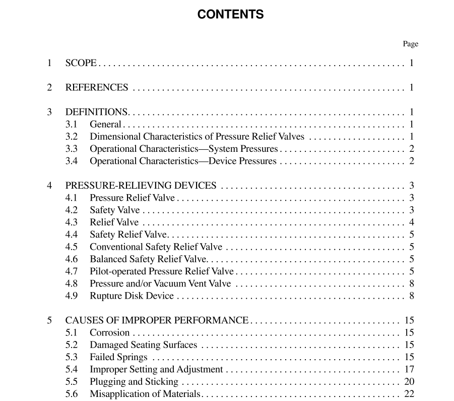
This recommended practice describes the inspection and repair practices for automatic pressure-relieving devices com- monly used in the oil and petrochemical industries. As a guide to the inspection and repair of these devices in the user’s plant, it is intended to ensure their proper performance. This publication covers such automatic devices as pressure relief valves, pilot-operated pressure relief valves, rupture disks, and weight-loaded pressure vacuum vents. The scope of this recommended practice includes the inspection and repair of automatic pressure-relieving devices commonly used in the oil and petrochemical industry. The recommendations in this publication are not intended to supersede requirements established by regulatory bodies. This publication does not cover weak seams or sections in tanks, explosion doors, fusible plugs, control valves, and other devices that either depend on an external source of power for operation or are manually operated. Inspections and tests made at manufacturers’ plants, which are usually covered by codes or purchase specifications, are not covered by this publication. This publication does not cover training requirements for mechanics involved in the inspection and repair of pressure- relieving devices. Those seeking these requirements should see API 510, which gives the requirements for a quality con- trol system and specifies that the repair organization maintain and document a training program ensuring that personnel are qualified.
3 Definitions
3.1 GENERAL 3.1.1 car seal: A self-locking seal that when placed in position and closed, locks and must be cut with wire cutters or physically broken to be removed. Local jurisdictional requirements may specify the acceptable method(s) of sealing or locking block valves. 3.1.2 non-reclosing pressure relief device: A pres- sure relief device, which remains open after operation. A manual resetting means may be provided. 3.1.3 pin-actuated device: A non-reclosing pressure relief device actuated by static pressure and designed to func- tion by buckling or breaking a pin which holds a piston or a plug in place. Upon buckling or breaking of the pin, the pis- ton or plug instantly moves to the full open position. 3.2 DIMENSIONAL CHARACTERISTICS OF PRESSURE RELIEF VALVES 3.2.1 effective discharge area: A nominal or computed area used with an effective discharge coefficient to calculate the minimum required relieving capacity for a pressure relief valve per the preliminary sizing equations contained in API RP 520. API Std 526 provides effective discharge areas for a range of sizes in terms of letter designations, “D” through “T”. 3.2.2 huddling chamber: An annular pressure chamber located downstream of the seat of a pressure relief valve for the purpose of assisting the valve to achieve lift. 3.2.3 inlet size: The nominal pipe size (NPS) of the relief device at the inlet connection, unless otherwise designated. 3.2.4 lift: The actual travel of the disk away from the closed position when a pressure relief valve is relieving. 3.2.5 outlet size: The nominal pipe size (NPS) of the relief device at the discharge connection, unless otherwise designated. 3.3 OPERATIONAL CHARACTERISTICS— SYSTEM PRESSURES 3.3.1 accumulation: The pressure increase over the max- imum allowable working pressure of the vessel allowed during discharge through the pressure relief device, expressed in pres- sure units or as a percentage of MAWP or design pressure. Maximum allowable accumulations are established by appli- cable codes for emergency operating and fire contingencies. 3.3.2 design pressure: The design pressure along with the design temperature is used to determine the minimum permissible thickness or physical characteristic of each vessel component as determined by the vessel design rules. The design pressure is selected by the user to provide a suitable margin above the most severe pressure expected during nor- mal operation at a coincident temperature. It is the pressure specified on the purchase order. This pressure may be used in place of the maximum allowable working pressure in all cases where the MAWP has not been established. The design pressure is equal to or less than the MAWP.
