API RP 1639 pdf download
API RP 1639 pdf download.Owner/Operator’s Guide to Operation and Maintenance of Vapor Recovery Systems at Gasoline Dispensing Facilities
1 Purpose and Scope
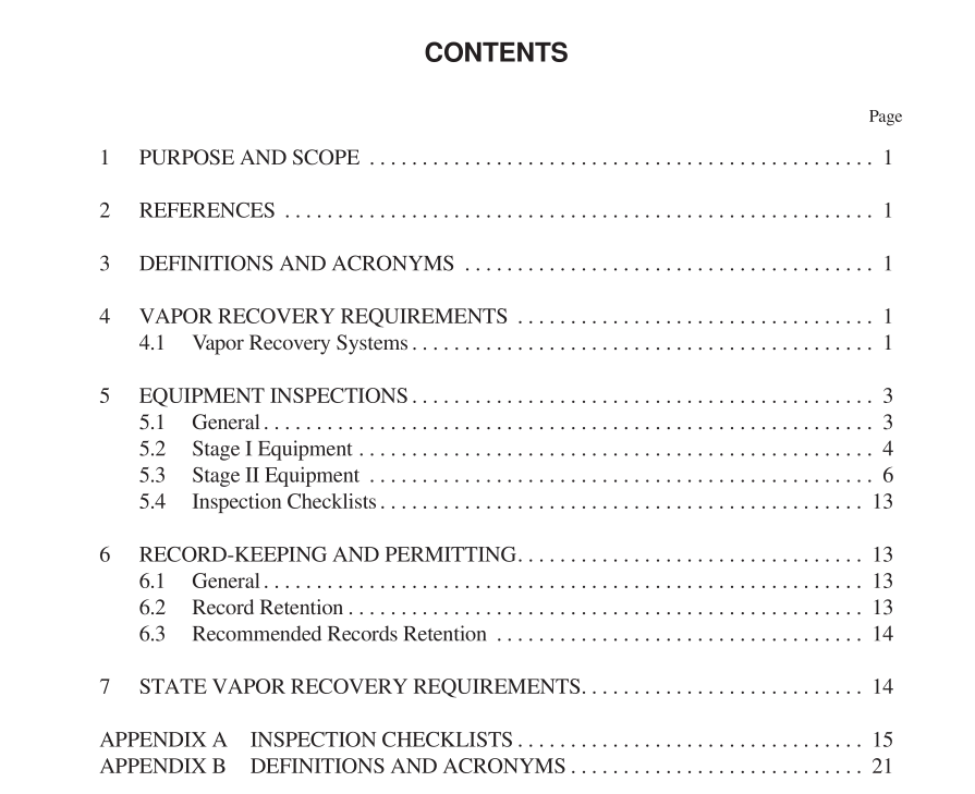
This Recommended Practice (RP) is designed to provide guidance to owners and operators of gasoline dispensing facilities (GDF) to effectively operate and maintain Stage I and Stage II vapor recovery systems. This guide does not address the maintenance required by qualified service techni- cians to perform periodic testing and major system repairs. Federal and/or State regulatory agency certified or approved vapor recovery systems/equipment must be used to maintain the efficiency of the vapor recovery system. The appropriate state and/or locality should be contacted individually for site- specific requirements. This RP recommends the need for periodic inspections of Stage I and Stage II equipment. The equipment and the crite- ria for inspection are identified in highlighted text with a cor- responding letter that indicates the frequency of the inspection. That is, a ( D ) represents a recommendation for a daily inspection; ( W ) recommends a weekly inspection; ( M ) recommends a monthly inspection; and ( A ) recommends an annual inspection. Appendix A is a suggested inspection checklist for the equipment and criteria identified in the text.
4 Vapor Recovery Requirements
4.1 VAPOR RECOVERY SYSTEMS 4.1.1 Stage I vapor recovery involves the return of vapors stored in the underground storage tank (UST) back to the tank truck during product delivery. Vapors in the underground tank headspace, i.e., the area in the tank above the liquid level, are displaced by the gasoline entering the tank during delivery. Headspace is also known as ullage. A flexible hose, provided by the transport company, connects the storage tanks providing a path for the vapors to return to the truck. Vapors in the truck are then returned to the distribution terminal for processing. Stage I vapor recovery is required by state and local regula- tions in most of the United States. Stage II vapor recovery is required in certain air quality nonattainment areas by federal regulations, and is administered by the states. Stage II regula- tions include some requirements for Stage I equipment.There are two types of Stage I systems: a two-point (dual) system, which uses separate product and vapor connections on the underground tank; and a coaxial system, which uses a single connection fitting to the underground tank. 4.1.1.1 Two-point (Dual) System The delivery of product and recovery of vapors in a Stage I two-point system occurs through separate connections (see Figure 1). The product is delivered (dropped) by gravity through a full connection and the vapors are returned through a separate vapor connection. The fill connection is fastened to a submerged fill tube that must have its discharge opening entirely submerged when the liquid level is 12 inches above the bottom of the storage tank. (Local requirements may require the installation to be no higher than 6 inches.) The vapors are recovered through the second opening in the top of the storage tank and transferred to the tank truck through the vapor hose. 4.1.1.2 Coaxial System The delivery of product and recovery of vapors in a Stage I coaxial system occur through a single coaxial submerged fill tube, which is simply a tube inside a tube (see Figure 2). The product is delivered through the inner tube and the vapors are recovered through the annular space between the walls of the inner and outer tubes. As with the dual system, the inner product tube must be entirely submerged when the liquid level in the tank is 12 inches or more while the outer vapor tube is in the top of the tank. (Local requirements may allow the installation to be no higher than 6 inches.) The coaxial submerged fill tube may be either fixed in position or spring-loaded (moveable) with a vapor seal simi- lar to the dry break adapter seal in the dual system. Unlike the fixed version, the spring-loaded version has a flange around the edge of the inner tube. A gasket is seated on the top sur- face of the flange.
