API Publ 4712 pdf download
API Publ 4712 pdf download.Characterization of Fine Particulate Emission Factors and Speciation Profiles from Stationary Petroleum Industry Combustion Sources
Dilution Stack Gas Samples Dilution sampling was used to characterize PM2.5 including aerosols formed in the near-field plume. The dilution sampler extracted a sample stream from the stack into a mixing chamber, where it was diluted approximately 21:1 with purified ambient air. Because PM2.5 behaves aerodynamically like a gas at typical stack conditions, the samples were extracted nonisokinetically. A slipstream of the mixed and diluted sample was extracted into a residence time chamber where it resided for approximately 80 seconds to allow time for low-concentration aerosols, especially organics, to condense and grow. The diluted and aged sample then passed through cyclone separators sized to remove particles larger than 2.5 microns, after which samples were collected on various media: high-purity quartz, Teflon ® membrane filters (TMF), and Teflon ® -impregnated glass fiber (TIGF) filters; a polyurethane foam (PUF)/Amberlite ® sorbent resin (XAD-4)/PUF cartridge to collect gas phase semivolatile organic compounds; and a Tenax cartridge to capture VOCs. Three samples were collected on three sequential test days.
The tests were performed on a gas-fired steam generator at Site C. The generator has a maximum heat input of 62.5 MMBtu/hr with an average rate of approximately 50 MMBtu/hr. The unit is an oil field steam generator with a single burner and retrofitted with flue gas recirculation. The generator was designed to fire both crude oil and natural gas, but is now only fired on natural gas. The generator appeared to be in good working condition during the test. Operating conditions during the test are given in Section 4. Process parameters monitored during testing include: burner gas rate; inlet water rate; steam quality; radiant section, steam and stack temperature; and excess oxygen. SAMPLING LOCATIONS Figure 2-1 provides an overview of the generator process and the sampling and monitoring locations. Flue gas samples were collected from the stack. The single stack is equipped with a 3 feet by 10.5 feet rectangular sampling platform located approximately 25 feet above the ground, which is accessible via a ladder. There are two 4-inch diameter sampling ports on the stack which are at 45° to one another. The ports are threaded with a 4-inch nipple. The stack diameter at this elevation is 36 inches. The sample ports are located 16 and 29 inches (0.4 and 0.9 diameters) downstream and 104 and 91 inches (2.9 and 2.5 diameters) upstream of flow disturbances. Following velocity and O 2 traverses to check for uniform mixing, all sampling was performed at a single point in the center of the stack to facilitate co-location of the dilution tunnel and EPA Method 201A/202 probes.
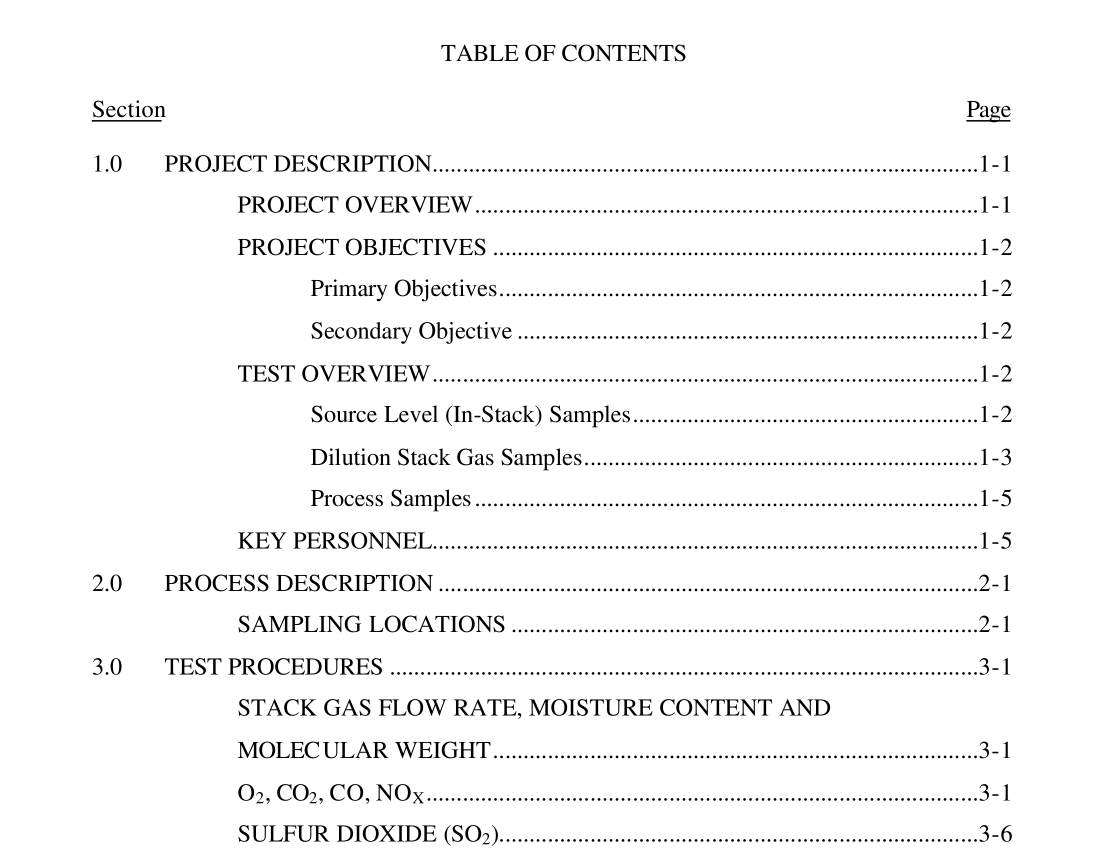
An overview of the sampling and analysis procedures is given in Table 3-1. Figure 3-1 shows the testing chronology for the dilution tunnel and in-stack methods. The time of day for the start and finish of each measurement run is shown on the figure. For example, Method 201A/202 Run 1 began at 09:30 hours and finished at 15:30 hours on Thursday, October 21. Dilution tunnel testing and in-stack testing were performed concurrently. All samples were collected at approximately the same point in the center of the stack; the dilution tunnel and in-stack test method probes were co-located. Testing during Run 3 was halted before the 6-hour sample time due to a process upset. A change in fuel quality caused the oxygen levels in the flue gas to drop, and the unit was not able to automatically adjust to the low levels. STACK GAS FLOW RATE, MOISTURE CONTENT AND MOLECULAR WEIGHT An S-type Pitot tube (EPA Method 2) was used to determine the average stack gas velocity and volumetric flow rate. Stack gas molecular weight was calculated in accordance with EPA Method 3. Moisture content of the sample was determined based on weight gain of the impingers used in the Method 201A/202 train according to EPA Method 4. A full velocity traverse of the stack was performed before and after each test to determine total stack gas flow rate.
