API MPMS 6.2 pdf download
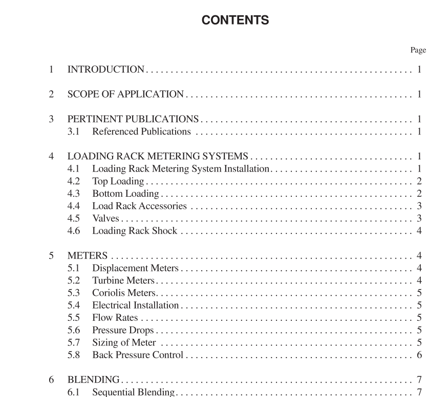
API MPMS 6.2 pdf download.Manual of Petroleum Measurement Standards Chapter 6—Metering Assemblies
4 Loading Rack Metering Systems
The loading rack metering systems described in this stan- dard are those that apply to transport-type truck facilities. The rack may be of a single-product/single-meter, single- product/multi-meter, or multi-product/multi-meter design. The design of the rack should allow one meter to be proved without interfering with the other meters involved in the loading operations.
4.1 LOADING RACK METERING SYSTEM INSTALLATION
Loading rack metering systems are designed to deliver accurate quantities of products into transport trucks for the subsequent delivery to remote locations. The metering config- urations may consist of single tally meters, single product meters, blend meters and additive meters. Since rack delivery meter volumes are considered in the terminal loss/gain deter- mination, the design, installation and operation of the meters is extremely important. It must be noted that the loading rack is usually the final opportunity to measure accurately, i.e., after the product leaves the loading rack, measurement errors are difficult to correct. Each meter must be proved under conditions as close to normal as possible. This would encompass the usual delivery flow rate into a tank prover. Another acceptable consideration is to prove via a pipe prover, with the prover return line deliv- ering to the transport truck. Some designs now include termi- nal return lines where, following the proving, the fluid is delivered back to the originating tank. When return lines are utilized, ensure that tank head pressure or pump inadequacy doesn’t cause an unacceptable decrease in flow rate. Caution should also be exercised to ensure adequate tank pump deliv- ery flow rate so that multiple product activity doesn’t cause a drop in flow delivery. 4.2 TOP LOADING Since State and Federal regulations govern the release of hydrocarbon emissions to the atmosphere, some forms of top loading may not be acceptable. Top loading (see Figure 1) requires the use of an overhead- loading arm to reach the loading dome hatches on the trucks. Loading arms should be designed to reach all domes on a sin- gle-bottom truck to avoid moving the truck. They should be equipped with an extended drop tube and either a deflector end or a 45º cut C tube end that will reach to the bottom of the truck and provide submerged filling. The loading arm should be in the same state of fill—either void or full—at the begin- ning and end of the loading operation to ensure measurement consistency.Top loading arms should be designed to swing up to avoid interfering with trucks entering the loading area and should be counterbalanced by a spring or weight to enable easy posi- tioning. When overhead clearance is insufficient for swinging the loading arm, the loading arm must be moved horizontally and the drop tube must be attached and detached at each load- ing dome on the truck. Meters for top loading racks can be located on the loading platform or near the ground. When the meter is located below the platform, the meter register shall be located to facilitate the reading of quantities by the truck loader, who shall be positioned to observe the filling of the compartment. A preset device, either local or remote, may be installed in any loading system to expedite loading operations. Access from the loading rack platform to the top of the truck is usually afforded by ramps, adjustable stairways, or platforms that are hinged to the side of the loading rack plat- form and can be swung down to the top of the truck. A hand- rail should be provided for the safety of truck loaders standing on top of the truck or platform.
