API MPMS 5.5 pdf download
API MPMS 5.5 pdf download.Manual of Petroleum Measurement Standards Chapter 5—Metering
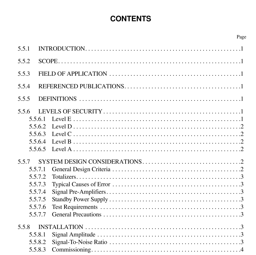
5.5.6.3 LEVEL C
A Level C system consists of automatic error monitoring and error indication at specified intervals by methods of com- parison. This level of security is intended to give protection against functional errors and failures and may be achieved by design methods. The time intervals for error monitoring may be subject to revision in the light of experience gained. Figure 3 illustrates a dual transmission system with a dual pulse comparator of simple design. If the pulses delivered become numerically out of a step, warning will be given by the com- parator (differential counter). Level C security will be defeated by other disturbances dealt with by higher level security systems. For example, simultaneous interference superimposed on both channels will not be detected because a numerical difference between channels is not caused. It is intended that this form of error monitoring be carried out periodically; the monitoring equipment may thus be shared with other metering systems. Level C security is inferred from the results obtained dur- ing the monitoring period.
5.5.6.4 LEVEL B
Level B consists of continuous monitoring, error indica- tion, and alarm signaling by methods of comparison. This level of security is intended to give warning of transients and other spurious influences, in addition to functional errors and failures. Figure 4 illustrates a dual transmission system with dual pulse comparator in which the pulse trains are continu- ously monitored for number, frequency, phase, and sequence and any irregularity is indicated. Simultaneous interfering pulses must be detected and indicated. Alarm is given if pulses are lost or gained on either channel. It may not be pos- sible to determine if pulses are lost on a channel or gained on the other channel.
5.5.6.5 LEVEL A
Level A consists of continuous verification and limited correction by methods of comparison. This level of security is intended to give protection against transients and other spuri- ous common mode influences, in addition to functional errors and failures. Figure 5 illustrates a dual transmission system protected against both dynamic faults arising from monitor- ing the duplicated pulses and by static testing the electrical integrity of the transmission circuits. The system should still operate as a Level E system if one of the transmission chan- nels fails. An incidental advantage of Level A is its ability to detect some mechanical faults in the transducer. Simulta- neous pulses caused by symmetrical interference are auto- matically rejected and do not influence the system. Other than a complete failure of one of the transmission channels, no attempt is made to automatically compensate for lost or gained pulses on either transmission channel. Alarm will be given in all circumstances when impaired pulses are received by the comparator. It may be desirable to provide redundancy in one or all of the elements shown.
5.5.7 System Design Considerations
5.5.7.1 GENERAL DESIGN CRITERIA
The most important consideration is to prevent the occur- rence of spurious pulses rather than rely upon the provision of verification circuitry to provide protection against the results of false measurement. The design approach shall, therefore, take into account the noise environment. Poorly designed units and inadequate regard for noise pick-up can seriously influence the performance of the equipment. Low-level high- impedance signals become attenuated by line losses, and the overall signal-to-noise ratio can further be impaired by the greater probability of noise in longer lines. A secure and reli- able pulsed-data transmission system will be achieved most readily by concentrating on the elimination of error sensitive elements. Addition of dual circuits or other techniques aimed at increasing security will guard against influences that are beyond the control of the designer. As a precaution, suppliers of signal processing equipment should be advised of radio frequencies used in close proxim- ity so radio frequency interference immunity can be investi- gated.
