API MPMS 4.9.2 pdf download
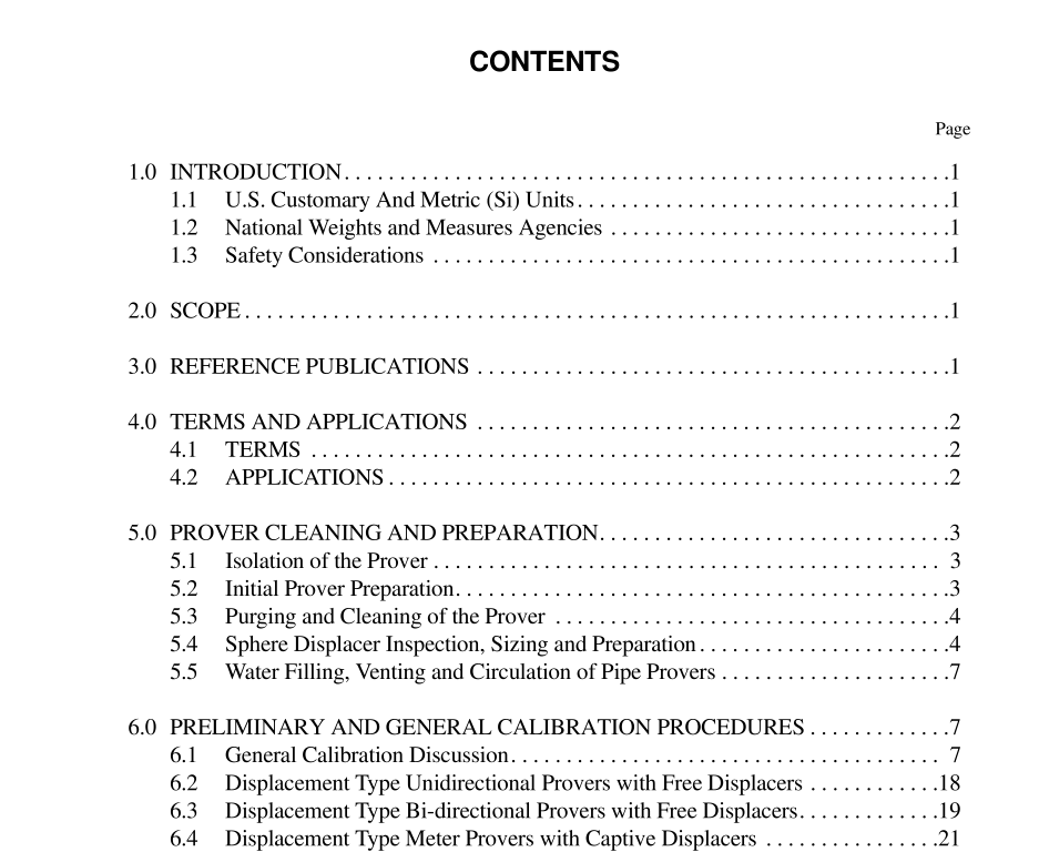
API MPMS 4.9.2 pdf download.Manual of Petroleum Measurement Standards Chapter 4—Proving Systems
2.0 Scope
This standard covers all the procedures required to determine the field data necessary to calculate a Base Prover Volume (BPV), of either Displacement Provers or Volumetric Tank Provers, by the Waterdraw Method of Calibration. It will enable the user to perform all the activities necessary to prepare the prover, conduct calibration runs, and record all the required data necessary to calculate the base volumes of displacement and tank provers. Evaluation of the results and trouble- shooting of many calibration problems are also discussed. Detailed calculation procedures are not included in this standard. For complete details the of calculations applicable to this stan- dard, refer to the latest edition of the API Manual of Petroleum Measurement Standards, Chapter 12, Section 2, Part 4, “Calcula- tion of Prover Volumes by the Waterdraw Method.”
4.0 Terms And Applications
There are no definitions unique to this document. However, the publications selected in section 3.0 may be referenced for defini- tions relating to the calibration of displacement and tank provers by the waterdraw method. Terms and symbols described below are acceptable and in common use for the calibration of meter provers. 4.1 TERMS 4.1.1 cessation of main flow: The moment when the full discharging water stream “breaks” and becomes a small trickle during the draining of a field standard test measure. 4.1.2 clingage: The film of liquid that adheres to the inside surface of a field standard test measure after it has been drained and is considered empty. 4.1.3 drain time: A fixed time period for completing the draining of a field standard test measure that is calibrated on a “to deliver” basis, as described on the Report of Calibration by the calibrating agency. The draining period starts at the cessation of main flow, and has the same duration as the draining time established when the test measure was calibrated. 4.1.4 field standard test measure: A vessel (usually of stainless steel) fabricated to meet a vigorous design criteria and specification, that is used as the basic standard of volume in the waterdraw calibration of volumetric provers. After calibration by NIST or another appropriate national metrology institute the test measure has a precise volume that is used to calculate the base volume of the prover under test. 4.1.5 “to contain” volume: A method of characterization of a field standard test measure, that determines its volume, at ref- erence temperature, when it is filled from a clean, dry, empty, condition. This volume is not utilized in the waterdraw calibration of provers. 4.1.6 “to deliver” volume: A method of characterization of a field standard test measure, that determines its volume, at ref- erence temperature, when it is emptied from its full condition, and drained in accordance with the prescribed draining time.
5.0 Prover Cleaning And Preparation
5.1 ISOLATION OF THE PROVER The prover and its auxiliary piping shall be isolated from all operating systems by either physical isolation with blinds, blind flanges, blanks, spectacles or double block and bleed valves to separate it from the upstream and downstream operating line pres- sures and products. A complete visual inspection should be made of the entire prover system to assure that the system is properly isolated. 5.2 INITIAL PROVER PREPARATION New or repaired provers are generally hydrostatically tested prior to placing into service. When a hydrostatic test is required, it shall be conducted prior to the waterdraw calibration. This ensures that the calibrated volume will not be altered by permanent pipe expansion, subsequent tightening of flanges, etc. Piston provers shall be waterdrawn using the same piston design and seals, both material and style, that are utilized in the prover’s normal meter proving operation. Substitution of spheres for the piston dur- ing calibration shall not be allowed. Connections to pipe work or flexible hoses are required for water circulation through the prover. These are typically 2 in. threaded connections, which should be as close to the calibrated section as practical. (If vents and drains are being considered for water- draw connections, their location should ensure that all the water used in the calibration will be circulated through the entire prov- ing system. This is necessary to maintain constant temperature in the calibration water.) Adequate water flow is required to launch the displacer in a pipe prover. High point vent valves should be inspected. If damaged, defective or leaking they should be repaired or replaced prior to the cali- bration. Vent valves, in good working order, are necessary for all prover calibrations, to ensure that all air or vapor has been vented from the prover prior to the start of each calibration pass.
