API MPMS 2.2C pdf download
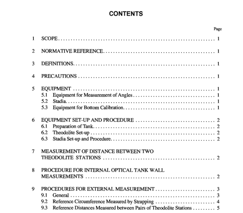
API MPMS 2.2C pdf download.Chapter 2-Tank Calibration
1 Scope
This part specifies a calibration procedure for applica- tion to tanks above 26 ft in diameter with cylindrical courses that are substantially vertical. It provides a method for deter- mining the volumetric quantity contained within a tank at gauged liquid levels. The measurement required to determine the radius may be made internally (Clause 8) or externally (Clause 9). The external method is applicable only to tanks that are free of insulation. 1.2 Abnormally deformed tanks; e.g., dented or non-circular tanks are excluded from this section, API MPMS Chapter 2. 1.3 This method is suitable for tilted tanks up to 3% devia- tion from the vertical, provided that a correction is applied for the measured tilt as described in API MPMS Chapter 2.2A. 2 Normative Reference
The following standard contains provisions which through reference in this text, constitutes provisions of this part of Chapter 2. At the time of publication, the edition indicated was valid. All standards are subject to revision and parties to agreements based on this section of Chapter 2 are encouraged to investigate the possibility of applying the most recent edi- tion of the standard indicated below. Members of API main- tain registers of currently valid API Standards.
5 Equipment
5.1 EQUIPMENT FOR MEASUREMENT OF ANGLES Equipment for measurement of angles as listed in 5.1.1 to 5.1.4 below. 5.1 . I Theodolites, with angular graduations and a resolu- tion equal to or better than 5 seconds. Each theodolite shall be mounted on a tripod which is firm and stable. The legs of the tripod shall be steadied by means of magnetic bearers when being used for the internal method. Repeat readings shall agree to within 5 seconds. 5.1.2 Low-power laser-beam emitter, equipped with a device such as a fiber-optic light-transfer system and a the- odolite-telescope eye-piece connection, by which the laser beam can be transmitted through a theodolite. The laser beam shall be coincident with the optical axis of the tele- scope. 5.1.3 Heavy weights, to set around the theodolite stations to prevent movement of the tank bottom plate. 5.1.4 Lighting, for use inside the tank to allow measure- ments to be read accurately. 5.2 STADIA 5.2.1 Stadia, 2 m long, such that the graduated length, between two marks, remains constant to within + 0.02 mm, at the temperature at which it is used. Note: Conversion to USC units is not recommended for use of the stadia. 5.3 EQUIPMENT FOR BOTTOM CALIBRATION Either: a. A liquid method, equipment as specified in Appendix E, or b. For a survey method, a theodolite, a dumpy level, a sur- veyor’s level or water-filled tubes.
6 Equipment Set-up and Procedure
6.1 PREPARATION OF TANK Fill the tank to its normal working capacity at least once and allow it to stand for a minimum of 24 hours prior to cali- bration. If the tank is calibrated with liquid in it, record the depth, temperature and density of the liquid at the time of calibra- tion. However, if the temperature of the wall surface could differ by more than 18°F (10OC) between the empty part and full part of the tank, the tank shall be completely full or empty. Do not make transfers of liquid during the calibration. 6.2 THEODOLITE SET-UP 6.2.1 Set up each theodolite with care, according to the procedure and instructions given by the manufacturer. 6.2.2 Set up the instrument to be stable. For the internal method, steady the bottom of the tank near the theodolite station by installing weights or other heavy objects around the station. Mount the legs of the theodolite on magnetic bearers to prevent the legs from sliding on the tank bottom. For the external method, drive the legs of the tripod fully home into the ground. 6.2.3 Set the bed plate of the instrument as near as possible to the horizontal. Note: This will ensure verticality of the swivel axis of the theodolite. 6.3 STADIA SET-UP AND PROCEDURE 6.3.1 Mount the stadia on the tripod according to the proce- dure and instructions given by the manufacturer. 6.3.2 Mount the stadia horizontally and perpendicular to the aiming axis by adjusting the device on the stadia. 6.3.3 Once setting-up is complete, lock the stadia in posi- tion and veri3 the horizontality and the perpendicularity.
