API IP St 1529 pdf download
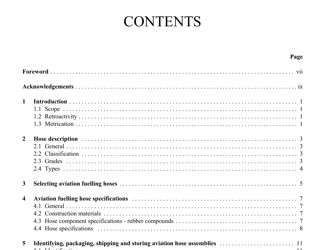
API IP St 1529 pdf download.AVIATION FUELLING HOSE AND HOSE ASSEMBLIES
Aviation fuelling hoses are installed on refuelling vehicles (hydrant servicers and fuellers) to deliver fuel to aircraft. Aviation fuelling hoses may also be used for the bottom loading and off-loading of fuellers and over- the-road tank trucks engaged in aviation product service as well as in other hydrant system servicing vehicles. Because of the pressures that may be present in a fuelling system, the aircraft fuelling hose selected should have a working pressure rating sufficient to withstand any surge or pressure increase that may be encountered during fuelling. In applications where hydrant pressures less than 140 kPa (20 psi) are encountered and the hydrant servicer is equipped with a booster pump, a Type F hose should be used on the hydrant-to-vehicle connection to ensure against collapse of the hose as a result of excessive suction caused by the booster pump. Type F hoses are also recommended when defuelling at a vacuum greater than 10 inches of mercury (5 psi). Note: Hoses should preferably be ordered with the couplings installed on both ends by the hose manufacturer or its authorised distributor or representative (see section 7). Manufacturers should advise purchasers/users as to the suitability or otherwise of the couplings supplied for reattaching by end users. Note: API/IP 1540, Design, construction, operation and maintenance of aviation fuelling facilities, section 7 gives advice on refitting couplings.
4.1 GENERAL
All of the specifications of this section must be met for each hose category except where noted. Fully collapsible hoses are not covered by these specifications. The manufacturer shall record test results demonstrating that the stated specifications have been satisfied. All required tests shall be carried out in full accordance with the provisions of sections 6.4.1 through 6.4.7 and sections 6.5.1 through 6.5.14. Manufacturers should provide certification as defined in sections 8.1 and 8.2.
4.2 CONSTRUCTION MATERIALS
The tube shall be of petroleum-resistant synthetic rubber compounds and shall have a thickness not less than 1,6 mm (0,063 inch) at any point. The tube shall be free from foreign materials or defects (e.g. holes, pitting, blisters, etc.). The reinforcement shall be braided or spiralled and be free from defects and geometrical irregularities. The cover shall be of petroleum-resistant rubber compounds. It shall have a thickness not less than 1,6 mm (0,063 inch) at any point for hoses with inside diameters of less than 50 mm (2 inch) and 2,0 mm (0,079 inch) for hoses with inside diameters of 50 mm (2 inch) or larger. The cover shall be free of defects (e.g. holes, pitting, blisters, foreign materials, etc.) and be resistant to damage by abrasion, cracking, and exposure to weathering, as defined by the tests in this publication.
4.3 HOSE COMPONENT SPECIFICATIONS – RUBBER COMPOUNDS
4.3.1 Tensile strength The tensile strength of the tube and cover shall be at least 7 000 kPa (1 000 psi). 4.3.2 Minimum elongation The minimum elongation of the tube shall be 250 % of its initial length. The minimum elongation of the cover shall be 300 % of its initial length. 4.3.3 Volume increase The volume of the tube when immersed in Reference Fuel B or a mixture of 30 volumes of toluene and 70 volumes of isooctane, as described in ASTM D 471, shall not increase more than 50 %. The volume increase of the cover under the same test conditions shall not exceed 75 %. 4.3.4 Fuel-soluble matter The hose inner tube after being immersed in the test fluids as described in 4.3.3 shall not yield residual soluble matter in excess of 4 % of the original mass of the test portion for hose types C, E and F. For Type CT hose, this limit is set at 6 %.
