API IP Spec 1590 pdf download
API IP Spec 1590 pdf download.SPECIFICATIONS AND QUALIFICATION PROCEDURES FOR AVIATION FUEL MICROFILTERS
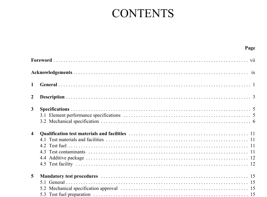
3.1.3 Flow rate Elements with a nominal 150 mm (nominal 6 in.) outside diameter shall meet the performance specification at a minimum flow rate of 10 l/sec/m of effective media length (equivalent to 6 l/min/cm or approximately 4 US Gal./min/in). Manufacturers may qualify elements at higher flow rates if they wish. Note: This flow rate is specified for qualification purposes only. Since element life in a given application is a function of both dirt loading and flow rate, it is recommended that the purchaser consult with the microfilter supplier to establish the optimum flow rate/vessel size for that application. For elements with outside diameters different to that specified above it is not possible to prescribe a minimum qualification flow rate. Manufacturers offering such equipment are advised to qualify at a flow rate maximised for the level of influent dirt indicated in 5.4. 3.1.4 Differential pressure The manufacturer shall state the average differential pressure across a new element operating at the qualification flow rate with clean, dry fuel in technical literature intended to communicate differential pressure based change out requirements.3.2.2.2 Materials of construction All metal parts in contact with the fuel shall be free of zinc, cadmium and copper. Metal components of elements shall be non-corroding. All materials shall be chemically compatible with the fuel. The element media, gaskets and sealing materials shall not deteriorate on exposure to fresh or salt waters. All seals shall be of Viton A, Buna N or equivalent. Under no circumstances is cork or rubber-impregnated cork an acceptable substitute. 3.2.2.3 Element identification Each individual element shall be permanently marked with the manufacturer’s symbol, element model number and/or the nominal rating of the element (in µm) and the date of manufacture. Where possible, the identity of the element should be located so that it can easily be seen when installed in the vessel. Any materials used to mark the element shall not contribute to the contamination of, or be affected by, aviation fuels. 3.2.2.4 Element packaging Elements shall be packaged for shipment so that mechanical damage and contamination by dirt and water are prevented. The packaging shall include element installation instructions including, as a minimum, the recommended element fixing torque and, as necessary, information on fasteners for mounting adapters, end cap nut sizes, etc.
3.2.3.2 Design codes Microfilter vessels shall be designed and constructed to conform to the latest issue of the ASME Boiler and pressure vessel code, Section VIII: Rules for construction of boilers and pressure vessels, or other recognised equivalent pressure vessel code agreed by the purchaser. 3.2.3.3 Design pressure Unless otherwise specified by the purchaser the vessel design pressure shall be no less than 1 035 kPa (150 lbf/in 2 ). The element mounting assembly shall be designed to withstand a differential pressure no less than 750 kPa (110 lbf/in 2 ) in the direction of normal flow. Note: For applications where the microfilter may be converted to a filter monitor, the purchaser should specify the design differential pressure of the element mounting assembly. (Compliance with API/IP 1583 is recommended.) 3.2.3.4 Hydrostatic test pressure Each microfilter vessel body shall be hydrostatically tested to 1 550 kPa (225 lbf/in 2 ) or 1,5 times the design pressure specified by the purchaser. The upstream side of the mounting assembly shall be hydrostatically tested with all ports sealed to a test pressure of no less than 750 kPa (110 lbf/in 2 ). Note: For applications where the microfilter may be converted to a filter monitor, the purchaser should specify the hydrostatic pressure testing requirement (all ports sealed) of the mounting assembly. (Compliance with API/IP 1583 is recommended.) 3.2.3.5 Piping connections All main fuel piping connections larger than 38 mm (1,5 in.) nominal bore shall have pressure ratings no less than that of the vessel and shall be flanged. Connections of types other than flanged may be substituted if specifically requested by the purchaser. Note: Fire safety issues should be considered when specifying connections.
