AS 2809.2 pdf download
AS 2809.2 pdf download.Road tank vehicles for dangerous goods
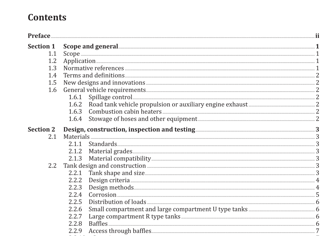
1.6 General vehicle requirements
1.6.1 Spillage control Any hot component shall be protected in the event of spills or leaks, by a shield or deflector. The spillage hazard requirements of AS 2809.1 Clause 2.1.15 and the following requirements shall apply: (a) The distance between a spillage shield and any cargo-carrying component shall be not less than 75 mm. (b) The minimum distance between any hot component and the spillage shield shall be not less than 50 mm. (c) Either of the dimensions in Items (b) and (c) may be reduced to not less than 25 mm as long as the total between the hot component and cargo carrying component is not reduced below 125 mm. NOTE Consideration should be given to routing of pipe work away from brakes. 1.6.2 Road tank vehicle propulsion or auxiliary engine exhaust The engine exhaust system shall conform with the following requirements: (a) The engine exhaust outlet shall not discharge within 1 m of any cargo connection point, vent or cargo carrying component opening. (b) No part of an engine exhaust system shall be located within 200 mm of any cargo carrying component. 1.6.3 Combustion cabin heaters Combustion cabin heaters shall conform with UNECE ADR. 1.6.4 Stowage of hoses and other equipment All loose accessories and removable equipment that are carried by the road tank vehicle shall be restrained in accordance with the NTC Load Restraint Guide. NOTE See Appendix A for Hazardous Area Classifications.
2.2.2 Design criteria
2.2.2.1 General The design shall allow for the combined effect of pressure (both circumferential and longitudinal stresses), torsion, shear, bending and acceleration of the tank as a whole. The effect of temperature gradients resulting from tank contents and ambient temperature extremes shall also be determined. When dissimilar materials are used, their thermal coefficients shall be used in calculation of thermal stresses. 2.2.2.2 Design loads The design loads for the tank, tank mounts and attachments shall be not less than 2 g applied along each axis (vertical, longitudinal and lateral). For the tank, this shall include the total tank mass, its accessories, and its cargo when filled to the safe fill level. The mass of the cargo shall be calculated from its actual density or 1 000 kg/m 3 , whichever is the greater. If a tank design is required to meet the provisions of an additional design code, such as International Maritime Dangerous Goods (IMDG) Code, the specific load cases provided in that code shall also apply. 2.2.2.3 Design pressure The design pressure shall be the summation of the following: (a) Pressure due to the liquid head (calculated from its actual density or 1 000 kg/m 3 , whichever is the greater). (b) Vapour pressure (minimum of 20 kPa for small compartment and large compartment R type tanks, or minimum of 30 kPa for large compartment U type tanks). NOTE Tanks designed to conform with this Standard are free venting. However, they may be subject to pressure cycles depending upon the venting, the product vapour pressure and the operating temperatures. As such, this could require consideration from a fatigue point of view.
2.2.3 Design methods
2.2.3.1 General The tank design shall be conducted by calculation or finite element analysis. The thickness of the shell, heads, bulkheads and baffles shall be not less than that specified in Table 2.2.12. 2.2.3.2 Calculation The tank and its supports and connections shall be designed in accordance with AS 3990, AS 4100, AS/NZS 4673 or AS/NZS 1664.1 and AS/NZS 1664.2, as appropriate, with the following qualifications: (a) Static strength — The tank, tank mounts and attachments shall be designed using the design loads and pressures given in Clause 2.2.2. The design loads along each axis shall be considered separately from one another and each shall include the design pressure. (b) Fatigue strength — Unless fatigue resistance has been demonstrated by field experience or supervised tests, fatigue stresses shall be calculated and added to the stress calculated for the stationary vehicle.
